

Interior Construction (Crew Area)
Here the various reinforcements on the topsides can be looked at in some detail.
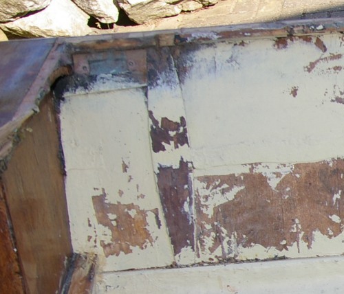
The topsides are made from 16th inch ply, with the external plys oriented vertically. This means several joints along the topsides. Clearly the builder didn't fancy making many scarf joints, so the ply is in fact butt jointed. In this first photo, of the port side with the buyancy tank just creeping into the photo on the left, you can see the reinforcement over the join, wider in the centre than where it meeets the chine and gunwhale. Its just possible to make out the line of glass tape that runs along the topside midway between chine and gunwhale as additional reinforcement.
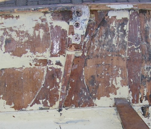
This second shot shows how the considerable loads from the shrouds are distributed. There are four parts to this complex component. Firstly a large wasp waisted piece of approx 3mm ply reinforceds the topside over the whole area. Then there is a tapered stripwood beam from chine to gunwhale, and (hidden) a second piece alongside it at the top. These are flush with the gunwhale. These two are covered by a piece of around 4mm ply which also covers the gunwhale, aking a very stiff but light structure. To the right of this is another topisde ply joints.
Thirdly , as we reach the bow tank, there is a carved and shaped piece of stripwood which runs from gunwhale to chine, actually glued over the chine rather than butted onto it. I suspect that the original mast support arrangement utilised a beam between these parts each side of the boat.
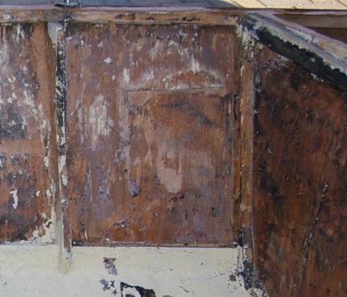
From this angle the shape of the this carved piece of stripwood can be seen. Note there is a similar frame, but not so wide at gunwhale level, which locates the front bulkhead. Curiously the front bulkhead support frame is outside the bouyancy tank between chines and gunwhale, but inside between chines and hog.
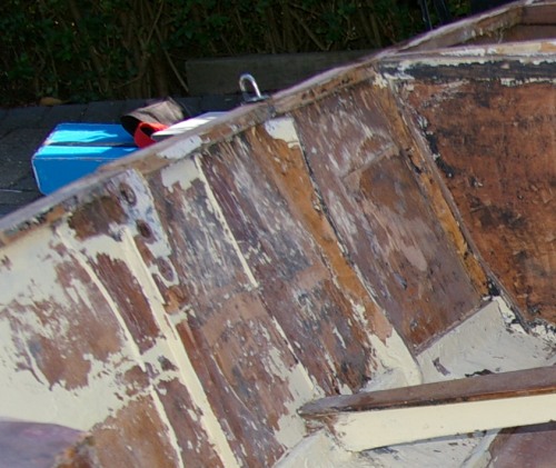
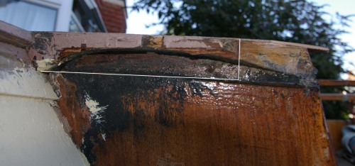
Here's another interesting detail. This structure interacts with the traveller beam. Its on the forward face of the side tank. Its another of these small "carved" frames, but this one is at deck level. It orginally had a piece of ply each side: the forward one is partially gone: the white line shows its shape. The inner end of the beam, where the ply stops, is shaped because the curved traveller beam is fastened to it. It helps take the loads from the traveller beam - which is a key component in making the hull more rigid and stopping it bending inwards and outwards under crew and rig loads - and distribute them into the hull structure. Like other such beams its carefully shaped - with the ply gone you can see the arch of its underside.
Interior Construction (Helm Area 1) Construction (Introduction)